


Project overview
This project involved the refurbishment of the 10 kV section of a military substation. The primary objective was to add ATS control functions to the existing secondary protection circuits to enable automatic transfer to a standby power source when the primary power source experiences a voltage drop or fault, thereby ensuring a continuous power supply for critical loads.
ATS devices play a crucial role in military projects, especially in the following aspects:
① Power supply continuity and high reliability
2 Improved emergency response capacity
③ Reduced administrative costs
5. Switching between different power supply modes
ATS scheme
The ATS device in this project acquires voltage and current signals from the two station service transformer accumulators, voltage signals from the two diesel generator accumulators, and position signals from five circuit breakers. The required ATS functions are as follows:
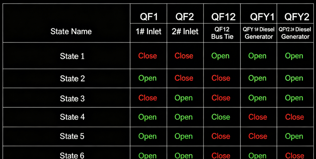
1) Normal operating conditions
2) Voltage deviation on input memory 1 only
3) Voltage deviation on input memory 2 only
4) Voltage drops on both input storage devices 1 and 2
Product solution
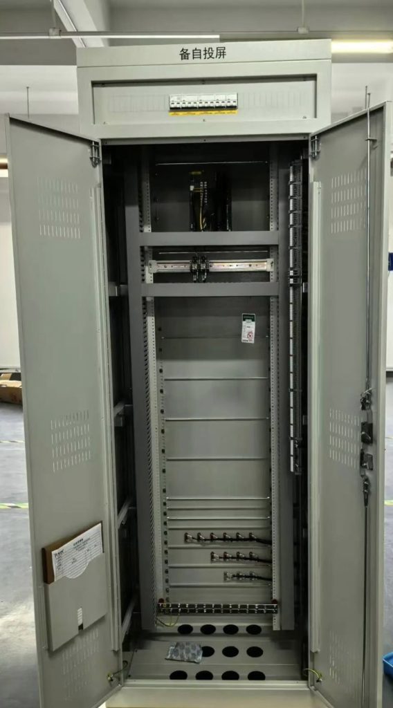
This project involved the installation of a new ATS panel with an ATS device in the 10 kV switchgear room and its integration into the existing control circuits.
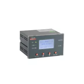
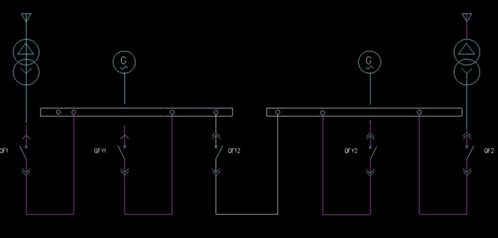
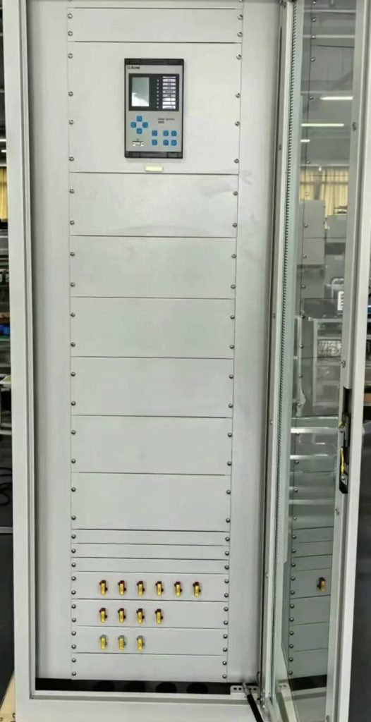
The 10 kV system consists of two station service transformer input accumulators, a bus tie-breaker, and two diesel generator accumulators. An AM5SE-B high-voltage ATS device was installed, wired, and mounted in the panel at the factory prior to shipment.
Upon arrival at the site, voltage signals, current signals, switch position inputs, and control power were connected to the panel terminals. The ATS device was then used to provide the opening and closing control for five circuit breakers.
At the same time, secondary wiring diagrams and terminal block drawings were created based on the site secondary schemes, providing the documentation for panel assembly and on-site integration.
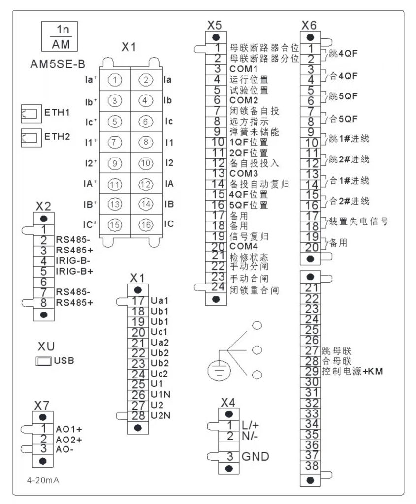
The connection configuration on the back of the device is shown in Figure 2.1.
Terminals X1.17–X1.20 are connected to the input voltage inputs of input memory 1;
Terminals X1.21–X1.24 are connected to the input voltage inputs of input memory 2;
Terminals X1.25–X1.26 are connected to the voltage inputs of diesel generator 1;
Terminals X1.27–X1.28 are connected to the voltage inputs of diesel generator 2.
Panel solution and on-site commissioning
In this project, the AM5SE-B high-voltage ATS protection device was installed in the ATS panel.
Partial terminal wiring and reserved external connections were completed during factory panel assembly. After delivery to the site, power, voltage, switch position, and other digital input signals were connected according to the design drawings. Appropriate output circuits were connected to the opening and closing circuits of the controlled switches.
Following on-site testing and commissioning, the system was successfully put into operation.
conclusion
Automatic transfer switches ensure an uninterrupted power supply and improve power supply reliability. They have become an important component of protection and control systems in modern power distribution technology.
The project described in this article used the AM5SE-B high-voltage ATS protection device to switch between different power supply modes. This not only improved power supply reliability and enabled integrated automation of the entire power distribution system, but also effectively reduced the workload of operating personnel and saved on labor costs.