















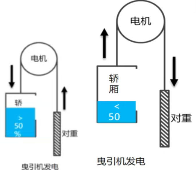
Elevators represent typical potential energy consumers. Under certain operating conditions, the drive motor switches from power consumption to power generation, continuously producing renewable electrical energy. This occurs primarily in three scenarios: First, during downward travel with a heavy load, when the cabin's weight exceeds the mass of the counterweight and the potential energy of gravity pulls the cabin downward, causing the motor to reverse and generate electricity; second, during upward travel with a light or no load, when the counterweight is heavier than the cabin, pushing downward and pulling the cabin upward, again causing the motor to reverse and generate electricity; and third, during deceleration, when the elevator slows down before reaching the destination floor, rapidly releasing its mechanical kinetic energy and converting it into electrical energy. Practical project trials have shown that the average energy savings per elevator after the installation of energy recovery systems can reach 30 % and, under optimal conditions, can even exceed 40 %. For commercial buildings or residential complexes with multiple elevators, the economic and social benefits of energy saving are considerable and offer a high degree of advertising and application potential.
I. Principle of energy recovery
Conventional, unmodified elevators lack an energy recovery function. The electrical energy recovered during elevator operation continuously increases the DC link voltage of the frequency converter. To ensure safe operation, this excess energy is dissipated as heat via braking resistors. This not only results in significant energy loss but also continuously increases the ambient temperature in the elevator's machine room, accelerating the aging of the system and impairing the elevator's operational stability.
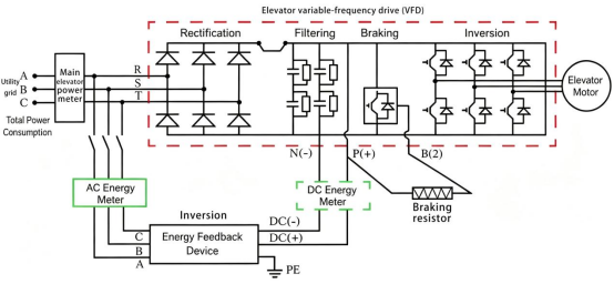
By installing a special elevator energy recovery system, the electrical energy recovered during operation can be reclaimed, processed, and fed back into the power grid for reuse. The entire energy recovery process comprises three main steps:
- Energy recovery: The alternating current generated by the elevator during operation is converted into direct current by the rectifier of the frequency converter and temporarily stored in the DC link capacitors of the frequency converter. This achieves the first energy recovery.
- Intelligent inversion: As soon as the DC voltage from the frequency converter reaches a preset threshold, the energy feedback device is activated with priority (over the braking resistor). Using core components such as an IGBT full-bridge inverter and a DSP microprocessor, the device converts the DC voltage into three-phase AC current that is compatible with the building's low-voltage network in terms of frequency, phase, and voltage.
- Purification and return: The inverted alternating current is filtered and purified by components such as filter chokes to effectively eliminate harmonics. After ensuring that the power quality meets the standards, the electricity is safely fed into the building's public AC grid and thus used for energy generation.
II. Relevant Standard Requirements
The national standard GB/T 32271-2015, "Energy feedback devices for lifts," regulates the technical parameters, test procedures, and safety of energy-saving feedback devices for lifts. It applies to unregulated variable voltage and frequency (VVVF) rectifier lifts with nominal voltages up to 400 V in TN-S power supply systems. The standard establishes mandatory requirements for key indicators such as energy efficiency, power quality, and operational reliability. The specific requirements are as follows:
Requirements for efficiency classification: Three efficiency levels are defined based on the load conditions: Conversion efficiency ≥ 85 % at 25 % load, ≥ 90 % at 50 % load and ≥ 95 % at 100 % nominal load.
Requirements for power quality: The total harmonic distortion (THDi) of the electricity fed back into the grid must be ≤ 5 %. In addition, specific limits are set for the content of odd and even harmonics to prevent disturbances in the public power grid.
Power factor requirements: When the output power of the device 50 % reaches its rated power, the power factor must be ≥ 0.90 to ensure grid stability.
Safety features: The device must be equipped with comprehensive protection mechanisms, including protection against islanding, overvoltage, undervoltage, short circuit, and open circuit. It must also be able to handle fault scenarios such as mains frequency deviations to ensure the safe and stable operation of the device and the grid.
This standard also specifies the test platform, conditions, and measurement methods for verifying these indicators. It mandates the use of high-precision bidirectional energy meters for simultaneous measurement at the DC input and AC output terminals of the device. By comparing the active energy at the DC input with the active energy at the AC output, the actual efficiency of the energy feedback device is calculated to ensure that the device meets the performance standards.
III. Selection procedure for energy feedback measurement in elevators
In accordance with the technical requirements of the national standard and considering the operating characteristics of energy feedback systems in elevators, retrofit projects require the use of measuring devices on both the DC side (device input) and the AC side (device output at the grid connection). This configuration covers the need for data monitoring of power generation, feedback quantity, power quality, and efficiency. Specifically, on the DC side, DC voltage, DC current, and bidirectional DC feedback energy are monitored. On the AC side, three-phase voltage, three-phase current, bidirectional active energy, reactive power, and apparent power are monitored. Simultaneously, power quality parameters such as current harmonics, harmonic content, power factor, and DC component in the entire system are monitored.
(1) Measurement method on the AC mains connection side (for the total energy consumption of the elevator and statistics on feedback energy)
Installation location: At the 380 V three-phase input line of the elevator distributor and at the mains connection of the energy feedback device.
Main purpose: To measure the energy drawn from the grid and the energy fed back into the grid by the elevator. This allows for the calculation of the elevator's total energy consumption and energy savings, and provides data for energy efficiency assessments.
- Wired network (standard for new construction projects):
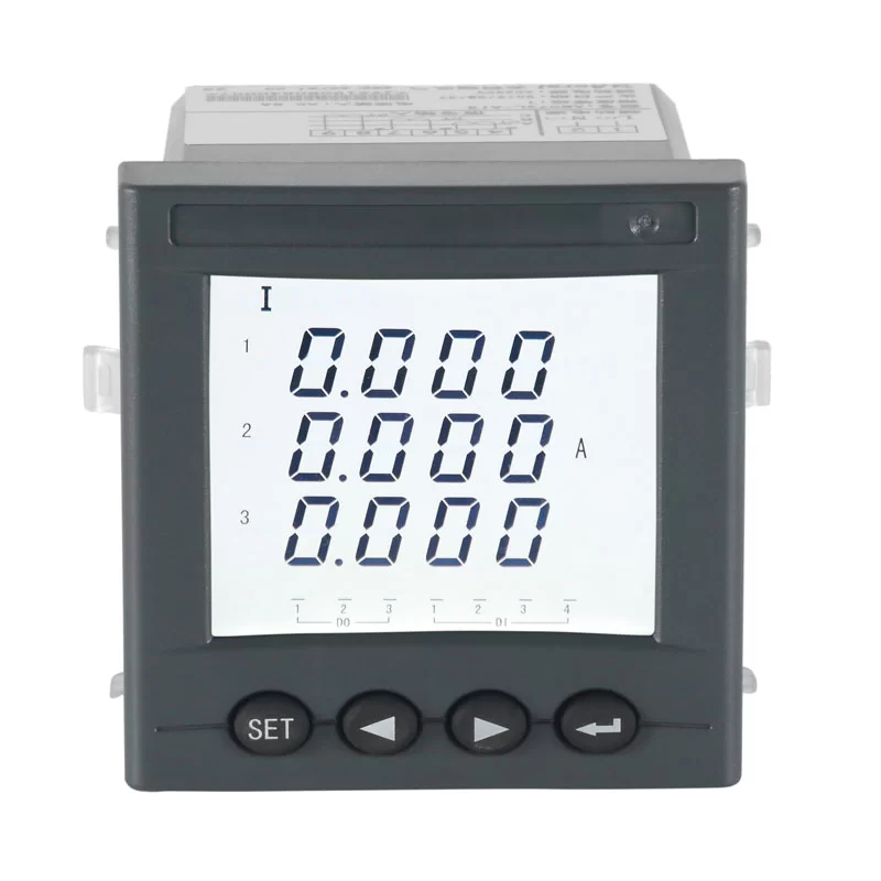
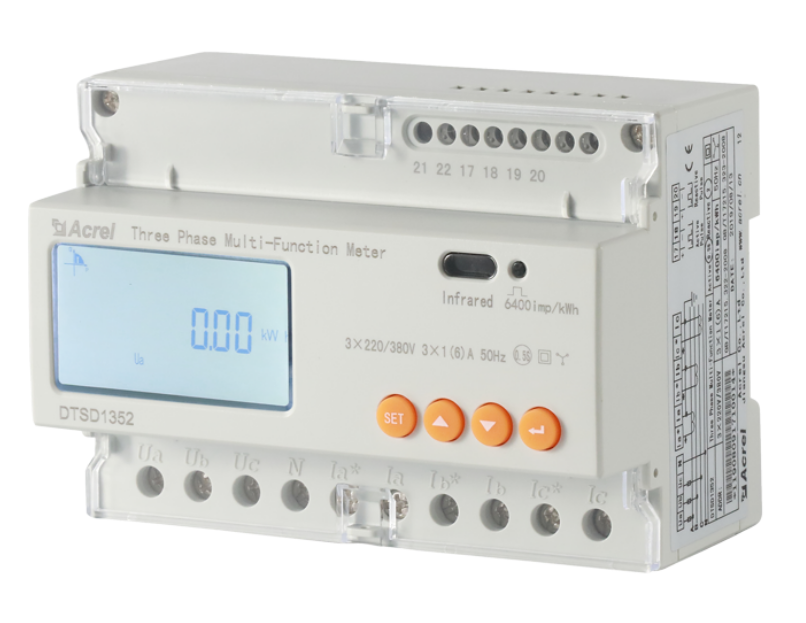
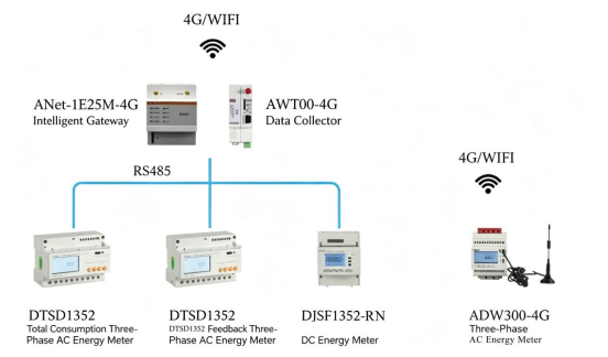
Selected device: Three-phase rail energy meter DTSD1352.
Device advantages: Supports three-phase, four-wire measurement, offering high-precision, bidirectional, four-quadrant measurement of class 0.5S. Compatible with external split-core current transformers. Suitable for retrofitting elevators in new residential and commercial buildings. The wired network connection is stable and reliable, making it suitable for standardized construction projects.
- Wireless IoT system (for retrofit projects with difficult cabling):
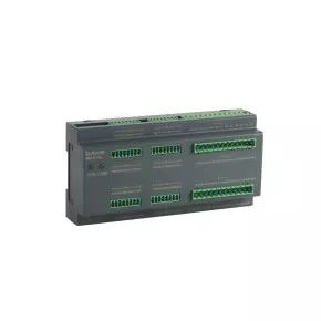
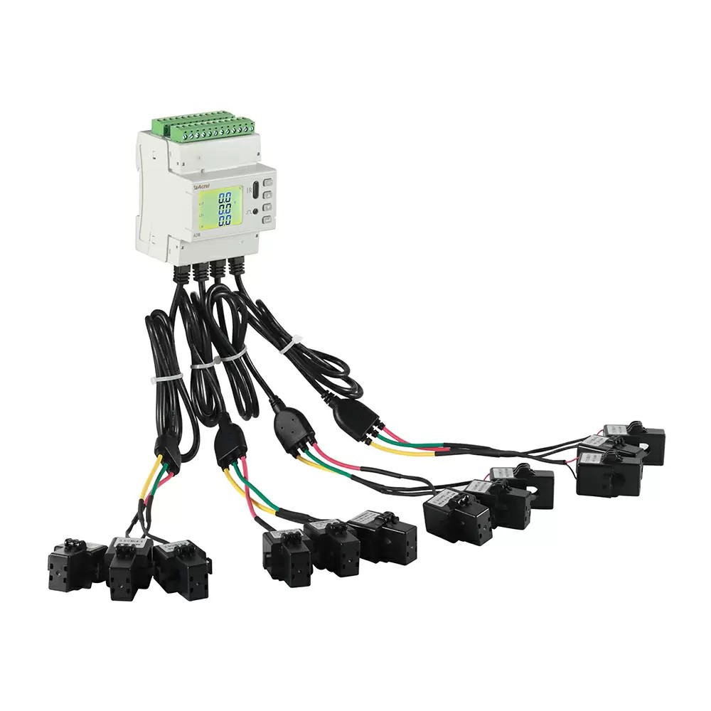
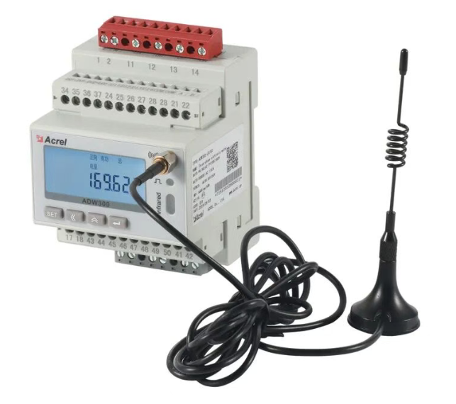
Selected device: ADW300 series wireless IoT electricity meter.
Device advantages: Optional 4G and WLAN communication modules support bidirectional transparent TCP transmission, enabling data to be uploaded directly to the cloud. No complex cabling is required, and installation can be carried out without power outages. The system is suitable for energy-efficient retrofitting of elevators in older residential areas or detached buildings.
(2) Measuring system for the DC feedback rail (for recording statistics on regenerative DC energy)
Installation location: On the DC-540V/750V rail side inside the energy feedback device.
Main purpose: Independent measurement of the elevator's regenerative DC power generation and calculation of the energy feedback device's efficiency. Also suitable for scenarios with integrated energy storage systems (capacitor/lithium battery) in the elevator for real-time monitoring of DC energy data during charging/discharging.
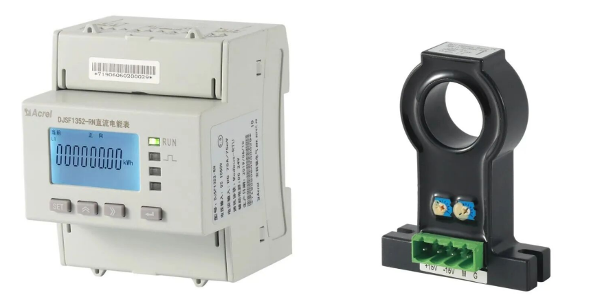
Selected device: Bidirectional DC energy meter DJSF1352-RN for rail mounting.
Device advantages: Voltage measurement range from 0 to 1000 V DC, supports the connection of 75 mV shunts and 0–20 mA/0–10 V Hall sensors. Optional dual-channel DC input for simultaneous monitoring of regenerative energy generation and the charging/discharging process of the energy storage system. Available in accuracy classes 0.5 and 1.0 for the highest precision requirements.
(3) Data collection and transmission scheme
Wired measuring instruments require special data acquisition devices to centrally collect, analyze and upload field instrument data to the cloud, thus ensuring stable data transmission.
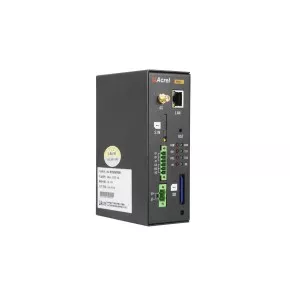
Selected devices: ANet-1E2SM-4G, AWT100-4G data concentrators.
Device advantages: The downstream side is compatible with the RS485 interface and the Modbus RTU standard protocol, making it compatible with all smart meters deployed on-site. The upstream side supports both 4G wireless and Ethernet transmission. The device features a rail mounting system suitable for various plant room scenarios and allows for flexible selection of the device model according to the requirements of the higher-level platform.
IV. Solution for the energy feedback management system of elevators
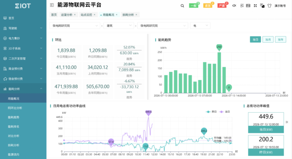
The solution is complemented by the Acrel-EIoT Energy IoT SaaS Cloud Platform, a proprietary, streamlined, and intelligent management platform. It supports device access via various protocols and synchronous access from multiple endpoints. The platform integrates comprehensive features such as real-time energy monitoring, system efficiency analysis, power quality diagnostics, push notifications for error messages, and automatic data report generation. This enables remote visualization, digitization, and intelligent management of elevator energy feedback systems. Users can quickly and easily commission the devices by scanning a QR code with a mobile app. Energy consumption data, operating parameters, and energy-saving statistics are accessible at any time via a web interface on a computer or mobile device.
Overview table for selecting system hardware and software:
| name | Picture | Model | function | Application |
| Three-phase AC electricity meter | | DTSD1352 | Three-phase current and voltage measurement Time-dependent energy measurement (TOU) Bidirectional (import/export) energy statistics Configuration of multiple time-based tariffs (TOU), compatible with various tariff models Accuracy class 0.5S RS485 interface | Power distribution line of the elevator or grid connection point for energy return |
| Multifunctional energy meter | | ADW300 | Three-phase measurement of electrical parameters Time-dependent energy measurement (TOU) Bidirectional (import/export) energy statistics Integrated split-core current transformers Installation possible under voltage RS485 interface 4G wireless communication Accuracy class 0.5S (when using external/standard current transformers) Accuracy class 1.0 (when using the integrated split-core current transformer solution) | Power distribution line of the elevator or grid connection point for energy return |
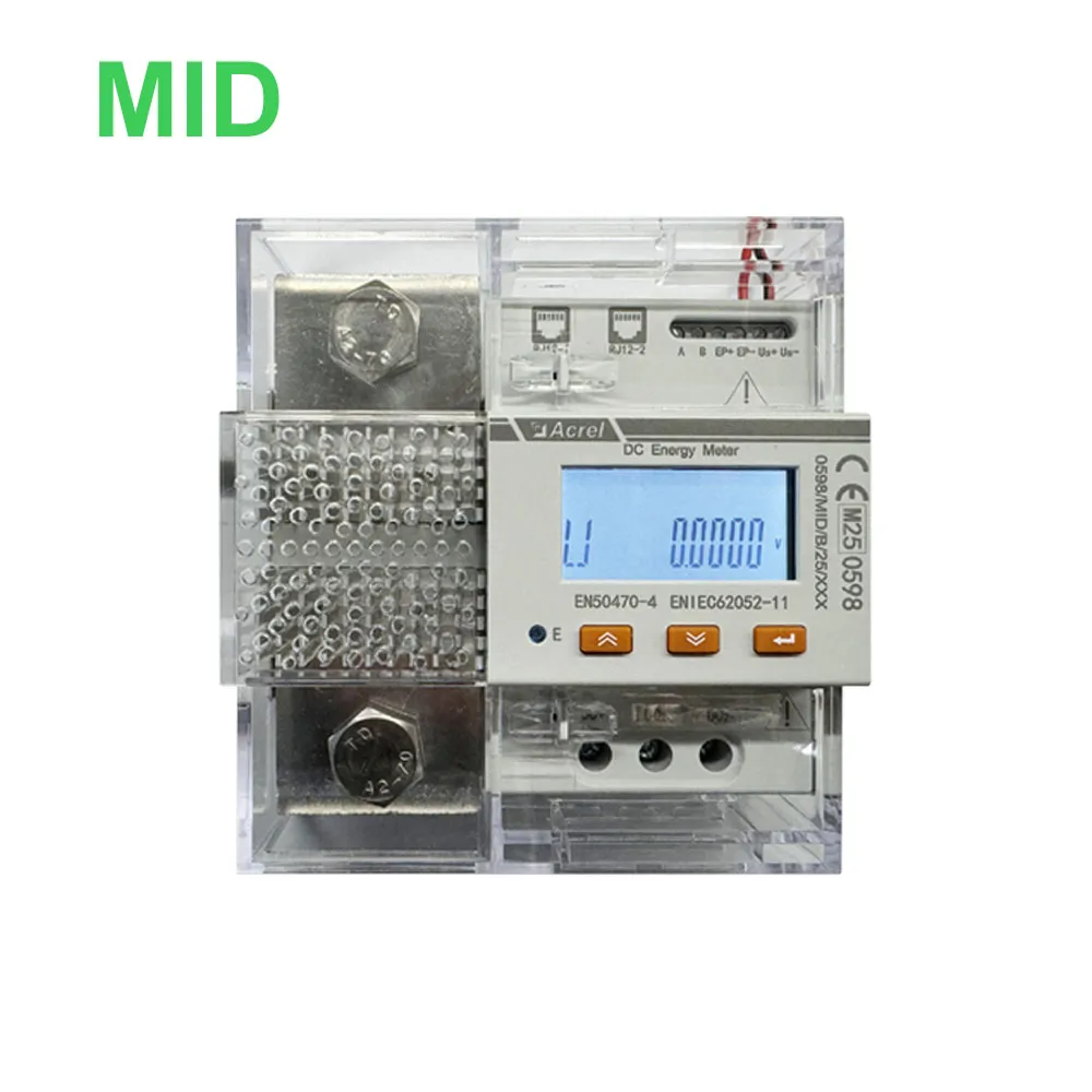
| DC energy meter | 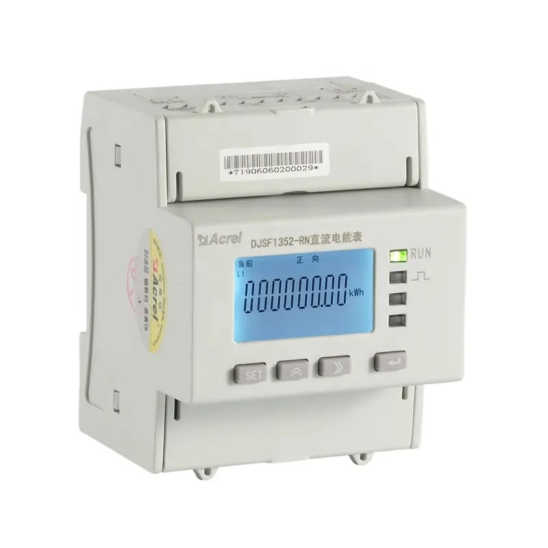 | DJSF1352-RN | Measures voltage, current, power and bidirectional (input/output) energy in DC systems Compatible with Hall sensors (optional) | DC output terminal for frequency converters (VFDs) of elevators |
| Current Hall sensor | 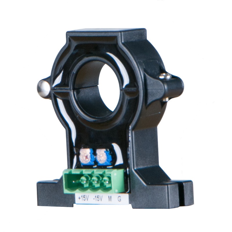 | AHKC-EKA | Measuring range: DC 0 to (5–500) A Output: DC current 4–20 mA Operating voltage: DC 12/24 V | Suitable DC energy meter |
| Intelligent Gateway |  | ANet-2E4SM | Integrated Linux operating system Network communication via socket mode Supports the upload of compressed data in XML format Offers ARS encryption and MD5 identity authentication for maximum security. Supports resumed data transfer (resumption after interruption) Supports various communication protocols: Modbus (RTU), Modbus TCP, DL/T645-1997, DL/T645-2007, IEC 60870-5-101, IEC 60870-5-103, IEC 60870-5-104 Compatible with various platforms | Compatible with Acrel EIoT or third-party platforms |
| Wireless router |  | AWT100-4G | Equipped with data acquisition and 4G upload capabilities, it utilizes wireless transmission mode and connects to the Acrel-EIoT Energy IoT Cloud platform. | Compatible with the Acrel EIoT Cloud platform |
| Energy IoT Cloud Platform | 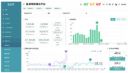 | Acrel-EIoT | Equipped with features such as data acquisition, data analysis, fault alerts, data reporting, and asset management. Supports QR code scanning via app for commissioning, essentially enabling "commission-free" setup. | Supports both private and public cloud deployments, with various data hosting options available. |